Archive for the ‘Electronics’ Category.

LED candle light with timer

LEDTimedCandle

I did a lot of research on battery powered LED candle lights circuits and code and was unable to find a time controlled LED candle light.

As I have some ATTiny13 left, I decided to use this little chip. As I want the LED to do a candle light for about 4hours and then stay of for another 20 hours, I need on timer and counter. Another timer/PWM is needed to immitate a candle flickering. But the ATTiny13 has only one timer. On the ATTiny13 you can either use the timer or PWM.

Fortunately the ATTiny has also a Watchdog timer that can be used to call an interrupt function. The watchdog runs with a separate 128kHz clock, independent from the CPU clock. The largest timeout is 8 seconds. So I need to count this 450 times to have one hour.

// watchdog interrupt
ISR (WDT_vect)
{
  sec8_counter++;

#ifdef USE_HEART_BEAT_LED  
  //flash heart beat LED
  digitalWrite(LED2, HIGH);
  delay(1);
  digitalWrite(LED2, LOW);
#endif
  
  if(sec8_counter>=HOUR_INTERVAL){
    sec8_counter=0;
    if(bLedIsOn==1){
      on_hours++;
      if(on_hours>=MAX_ON_HOURS){
        bLedIsOn=0; //switch to OFF mode
        off_hours=0;
      }
    }else{
      off_hours++;
      if(off_hours>=MAX_OFF_HOURS){
        bLedIsOn=1; //switch to ON mode
        on_hours=0;
      }
    }
  }
  wdt_reset();
}  // end of WDT_vect

The code makes the ATTiny13 sleep for another 8 seconds or light the LED. The ON phase is 4 hours and the sleep phase will be extended to 20 hours.

void loop ()
{
  //sleep 20 hours and work 4 hours
  noInterrupts();
  if(bLedIsOn==1){
    doCandle();
  }else{
    digitalWrite (LED, LOW); //ensure LED is OFF
   goToSleep ();
  }
  interrupts();
}  // end of loop

The sequence starts with the ON phase, when power is applied. In the ON phase I measure about 3mA and in the OFF phase the circuit needs 300µA.

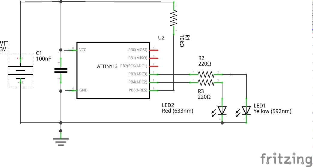
The circuit is documented in the Arduino code file. Running the ATTiny13 at lower clock than 9.6MHz did not change the power usage. But I switched to the 1.2MHz internal clock and disabled BOD (auto power down for low power) to get a longer runtime with two or three AA batteries.

UPDATE 2019/03/10: The wdt calculation is wrong and I changed the 450 cycles for one hour to 388. See github README for full update. The main issue is that the ATTiny13 datasheet says 128kHz but means 131072Hz and not 128000Hz and the wdt oscilator never cycles that fast but more or less at around 113000Hz.

https://github.com/hjgode/LEDTimedCandle/tree/master

CREDITS to all that share their knowledge, especially:

https://github.com/MCUdude/MicroCore

http://forum.arduino.cc/index.php?topic=200590.0

https://electronics.stackexchange.com/questions/74840/use-avr-watchdog-like-normal-isr

http://www.ece.cmu.edu/~koopman/lfsr/index.html

adsbox adsb receiver antenna rtlsdr gain

As adsbox did take too much CPU from my main server I moved adsbox to a banana pi zero w. Running Raspbian adsbox used about 200% of the 4 cores and 10% of the 512 MB headless system. That was OK for me and I wanted to extend the range of my rtlsdr antenne. I moved the antenna out side and was impressed about the exended range but nearby aircrafts did not show any more 🙁

As I want to see the nearby aircrafts, we are near düsseldorf in the landing lines and wanted the data of the aircrafts crossing the small home village 30km away from the DUS airport.

adsbox missed too much data or the rtlsdr dongle received too much signals. First I changed the adsbox call to use 4 threads for adsb decoding. That did not help.

Then I looked for the gain values to lower the reception signal strength. My rtlsdr RTL8232u supports gain values (found with rtl_test):

#Supported gain values (29): 0.0 0.9 1.4 2.7 3.7 7.7 8.7 12.5 14.4 15.7 16.6 19.7 20.7 22.9 25.4 28.0 29.7 32.8 33.8 36.4 37.2 38.6 40.2 42.1 43.4 43.9 44.5 48.0 49.6

I first started with 0.0 and got better nearby results but only a range of about 5km. Using 25.8 gives a range of 120km but too much airplanes (~39) and nearby losts. With the max gain I had more than 59 airplanes at a time. Finally I used 16.6, which still gives a range of 80km and ~5-10 airplanes.

Using the highest gain would give a very large range of ~250km but nearby signals get lost. And we ant to see mainly the nearby airplanes and now use a gain of 16.6.

The cpu usage is now down to 100% (quad core, so that is 25%) and the adsbox decocde threads are down to 15-25%.

FHEM: Battery powered Home Automation remote display using small OLED and MQTT

This is the successor of my MQTT remote display. It is battery driven and can so be placed where you want.

The main component is a Pololu U1V11F3, a step up/down converter with 3V3 output and an Enable input pin. Unfortunately the Enable pin is already clamped to Vin via a 100K resistor. For me I had to remove the small SMD resistor to have the circuit powered off normally. The R6/100K is located directly to the Enable in Input connectors of the Pololu board.

The Enable pin is then connected to GND via an 1M resistor to ground. Do not leave the Enable pin floating, it will sense a finger tip already and switch to on/off by accident.

Then I added a momentary switch and a 47K resistor between Vin (the battery Plus) and the Enable pin. If the switch is pressed, the converter starts and gives 3V3 on it’s Output pin. This powers the ESP12 and the OLED display. But only as long as you press the switch. So I added a Diode from GPIO14 of the ESP-12 to the Enable pin.

In the code, GPIO14 is set as output and immediately set to high. This will enable the converter even when the switch is released.

After some code cycles, the GPIO14 output is set to low and the power of the converter is shut down.

The converter will not drain the battery in shutdown mode. But you need to press and hold the switch 2 or 3 seconds until the code powers the Enable pin.

Electronics: Modify Cree like Motorcycle LED Fog Projector Light

U5, U3 U7 Cree LED light with 3000lm and 30W?

There are various cheap High Power LED motorcyle LED lights out there, all coming with different circuits but all with 3 Modes: High Beam, Low Beam and Strobe Light.

A friend baught some of these LED Lights and asked me to remove the Strobe and Low Beam. Unfortunately, non of the existing posts had the same circuit board inside. During my research and tests I blew one the pair. I hoped to get a known circuit driven Light by buying another pair with Devil Eye, a blue Angel LED circle which is specified with 12-80V.

Continue reading ‘Electronics: Modify Cree like Motorcycle LED Fog Projector Light’ »